UNIT 1: Computer Systems
Definition / System Model

This was our first note this unit which was a powerpoint presented by our teacher. some of the key definitions that I learned from this lession are:
-Computer: An electronic information processing system
-Software: The programs and other operation information for the computer
-Hardware: any physical component of a personal computer
-Application software: programs that do real work for the users
-System model: refers to the inputs, processing, memory, storage and outputs a system.
-Data: text, video, audio, or other inputs or outputs which are coded into binary infomation
Hardware research

For the hardware research assignment we had to choose one computer hardware from a list provided by our teacher. There were several options including CPU, motherboard, scanner, keyboard etc. however, the hardware that I chose was laser and Inkjet printers. After selecting one PC hardware, I had to create a powerpoint presentation that includes a brief history and overview of the hardware, how it operates, typical specifications, future tends and additional information. Firstly, I would like to discuss how a Laser printer works. A laser printer operates on the basic principal of static electricity. Laser printer works by first shining a laser beam across the drum which creates a electrostatic image, which is basically letters and images as electric charges, then the printer coats the drum with positively charged toner. The printer then gives the paper a negative charge so it attracts with the toner and lastly the paper goes through the fuser which melts the toner to the paper before it exist the printer. On the other hand, a inkjet printer works by placing tiny droplets on the the paper. furthermore, some of the typical specifications that I learned about are speed measured PPM (pages per minute), and resolution measured in dpi (dots per inches).
PC Custom Design & Purchase

For this assignment we were given a virtual budget of $1500 including taxes ($1327 before tax) to purchase a desktop PC online and then research and write a brief report with 4 section. For my custom pc I was able to get the Intel core i7 processor which one of the one of the fastest CPUs in the current market, an HD video card with 1GB RAM for maximum quality, and to support that I got a 21.5" LED monitor which provides crystal clear HD images through the HDMI port. Furthermore, this assignment really helped me learn that a computer is so interconnected and the parts must be selected wisely in order for the pc to successfully operate. For example one thing I learned was that the motherboard must have the same processor interface as the processor in order to properly function. The only thing I would do differently in the future is to purchase a creative and unique case for the pc.
UNIT TWO: Networking
Networking theory & devices

Before starting something new, I truly believe that background knowledge is very necessary, and to get the background, note taking is very essential. Therefore, our student teacher started this networking unit with a couple of notes. The first note that we took was on networking, where I learned the real definition of a network, which is a group of computers and/or other devices (i.e. printer) that are connected by some type of transmission media. We also learned about the types and styles of networks, which are; peer to peer, client server, local area network (LAN), metro area network (MAN), wide area network (WAN) and strike through. Furthermore, I also learned about physical topology, cables, basic components of a network, data communication, an simple ways to trouble shoot a network.
Network Design
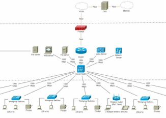
For this Assignment I had to create a network for high tech community school that have 8 computer labs with 28 PC's each and a networked printer in each room. Among them, 3 labs were for high end workstations (video, animation, and graphics) which needed a separate gigabit switch and a file server. I would say that this is one of the hardest assignments I have done in this course because finding the specific parts for this network was very difficult and time consuming. Among all this parts, the hardest part to find on the internet was a router with dual OC12 connecter. I also had trouble figuring out the amount of fiber optic cable needed because we were not given a specific distance. Another time consuming part about this assignment was making the network diagram on Smart Ideas because the connectors did not connect at 90 degree angles, and creating the layers of the network in straight since there were a lot of objects to move around. However, this assignment really helped strengthen my knowledge of how the connection of a network works. After completing this assignment, I realized how difficult it is to create the network of a school in real life.
First Robotics

On Friday March 2012, my class went to on a field trip to the Hersey Center to cheer for our school's robotics team called the Arrowbots. Our schools robotics team was participating in a nation wide competition presented by first robotics. FIRST is For Inspiration and Recognition of Science and Technology. This non-profit organization's mission is to inspire young people to pursue further studies and careers in the field of science, technology and engineering. Some of the tasks for the robots were to balance on a bridge, shooting hoops, and helping team members by colleting basketballs. This trips was very enjoyable because I was able see many amazing designs of robots that the other schools build and also see the excitement among the spectators. Overall, the arrowbots did very well in the competition, coming eleventh in raking.
Professional Certifications

Unit Three: Digital Circuits Technology
Binary / Hex Numbers

Computers are based on the binary numbering system, which consists of just two unique numbers, 0 and 1. All operations that are possible in the decimal system (addition, subtraction, multiplication, division) are equally possible in the binary system. For the computer, the binary system is more natural because of its electrical nature (charged versus uncharged). Because computers use the binary number system, powers of 2 play an important role. This is why everything in computers seems to come in 8s (2 to the 3rd power), 64s (2 to the 6th power), 128s (2 to the 7th power), and 256s (2 to the 8th power). Converting from binery to decimal or decimal can get very difficult using the power of two, therefore, programmers use Hexadecimal because because they map nicely onto the binary system since each hexadecimal digit represents four binary digits. Hexdecimal is a base-16 number system, which consists of 16 unique symbols: the numbers 0 to 9 and the letters A to F. For example, a decimal value 14 would be represented by the Hex number, E. It is easier for humans to read hexadecimal numbers than binary numbers.
Logic Gates

A logic gate is an elementary building block of a digital circuit . Most logic gates have two inputs and one output. At any given moment, every terminal is in one of the two binary conditions low (0) or high (1), represented by different voltage levels. The seven types of logic gates are:
- AND gate: The output Y is true if input A AND input B are both true. An AND gate can have two or more inputs, its output is true if all inputs are true.
- OR gate: The output Y is true if input A OR input B is true (or both of them are true).
An OR gate can have two or more inputs, its output is true if at least one input is true. - XOR: The output Y is true if either input A is true OR input B is true, but not when both of them are true. This is like an OR gate but excluding both inputs being true. The output is true if inputs A and B are DIFFERENT.
- NOT gate: The output Y is true when inputs A OR B are not true.
- NAND gate: The output Y is true if input A and input B are not true.
- NOR gate:The output Y is true if inputs A OR B are not true.
- XNOR gate: The output Y is true if inputs A and B are the same.
Electronic Circuit Theory and Breadboarding

Before starting to work on the breadboards we were given preliminary knowledge on electronics through a slide show presentation. Our class took a note on calculating volts, amperes, resistances using the Ohms law ( V = IR). I also learned about an electronic circuit which is a combination of power supply (battery generator, solar cells etc) and load devices(resistors, LED's capacitors etc) electrically by a conducting device (copper, aluminum etc) . I also learned the the schematic symbols for various electrical components including LED's, power, switch, transistor etc. I also learned the color coding system for finding the resistance of a resistor. Breadboarding was a concept that we learned in grade 10 and the concept is easy and very fun. we were told that our breadboard should be as flat and linear as possible.
Logic probe and Logic gates labs

For my first breadboarding assignment I had to create a logic probe similar to the one I made in grade ten however with more complex circuitry because we had to incorporate transistors which required more thinking skill. The function of a logic probe is to determine the digital output of either 1s of 0s which is indicated by the the LED's, so a high output would be represented by a red LED and a low output would be represented by a green LED. The logic probe was useful in my next lab in which we had to determine the type of a chip based on was is imputed and what signal it outputs through the logic probe. For the logic gate lab I had to work in a group of two's and our task was to wire 4 combinations of 2 inputs for four different integrated circuits, and record the output from your logic probe into each truth table. based on the inputs and outputs, we had to determine the type of logic gate. Overall, this was a very interesting assignment and I gained a lot of valuable knowledge on digital circuits.
Roulette LED project
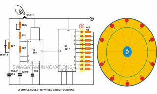
For my final assignment for unit three, I had to create an electronic roulette wheel. The digital chips that I used for this assignment were a LS555 timer chip which i previously used in grade ten, and a 4017 counter. This assignment required a lot of wiring which made it difficult for my to create a neat breadboard however, I was able to successfully mange that task by reducing the amount of wires and making them as flat as possible. Each pin in the 4017 chip had a specific order in which it would flash the LED so wiring it properly would be very important. I, at first, never knew the chip required you to wire the LED's in a specific order so I wired it in pin order (from pin 0 to 11). After realizing my mistake I had to rewire to my LED's but everything was done quickly. When everything was finished everything worked perfectly and I was able to help others with their circuit. Despite, the challenges that I had to overcome, I was successfully able to complete my roulette wheel.
Unit Four: Robotics and programing
Boe-bots

Unit four was required more interfacing skills because we had to work with both a hardware device (boe-bot) and software (pbasic). For this unit we were given a series of tutorials that taught my how to program the boe-bots using pbasic software. Our first program was to create a counting loop that displays a countdown sequence on Basic Stamp, used a for loop, for this program. We learned how to control LED lights using high and low commands and the pulsout command. The next part was to learn how the servo motor operates. Using the pulsout command, we learned of different combination that made the bot travel forwards, backward, left, right and etc. the major assignment for this unit was to create a code on pbasic that can navigate the robot to precisely trace an S pattern made of 1-foot segments using subroutines exclusively, with start & stop movements 'ramped up' and 'ramped down' accordingly. Subroutines simplify the coding process because instead of writing a code for every time for the same command a subroutine allows to create a variable that contains the code for that specific command which can easily be used by a simple command GOSUB variable name. The challenge was easy when I completed my distance calculations and subroutines but I needed to fine tune code especially on my distance calculations and 90 degree turns.
Summative: Boe-bot Navigation Assignment
Infrared navigation

For our Final Evaluation, we had to use our skills from the previous programing and navigation, we had to equip our bots with special navigation hardware and we had to use it to avoid objects or walls.we made a Wall Following program for the boe-bot, to start off, the PDF file guided us, we attached Resistors, Wires, LED's, and sensors, in to the breadboard on our boe-bot, then we programmed it, one sensor to follow the wall ( which was the left sensor for me), and one sensor to turn left (right sensor) when nothing is detected by it, and when both sensors detected something, its turns right. We made a program based on this, we first just copied off an example, of an program then we modified it to what we wanted to do, which was wall following. Using our skills from the previous programing and navigation, we had to equip our bots with special navigation hardware and we had to use it to avoid objects or walls.
